

Scroll Down
Scroll Down
We deliver high-precision microwave and millimeter wave components to commercial industries where performance and reliability are non-negotiable.
Read MoreWith applications spanning land, sea, air, and space, our solutions for defense applications are engineered to excel in the harshest environments.
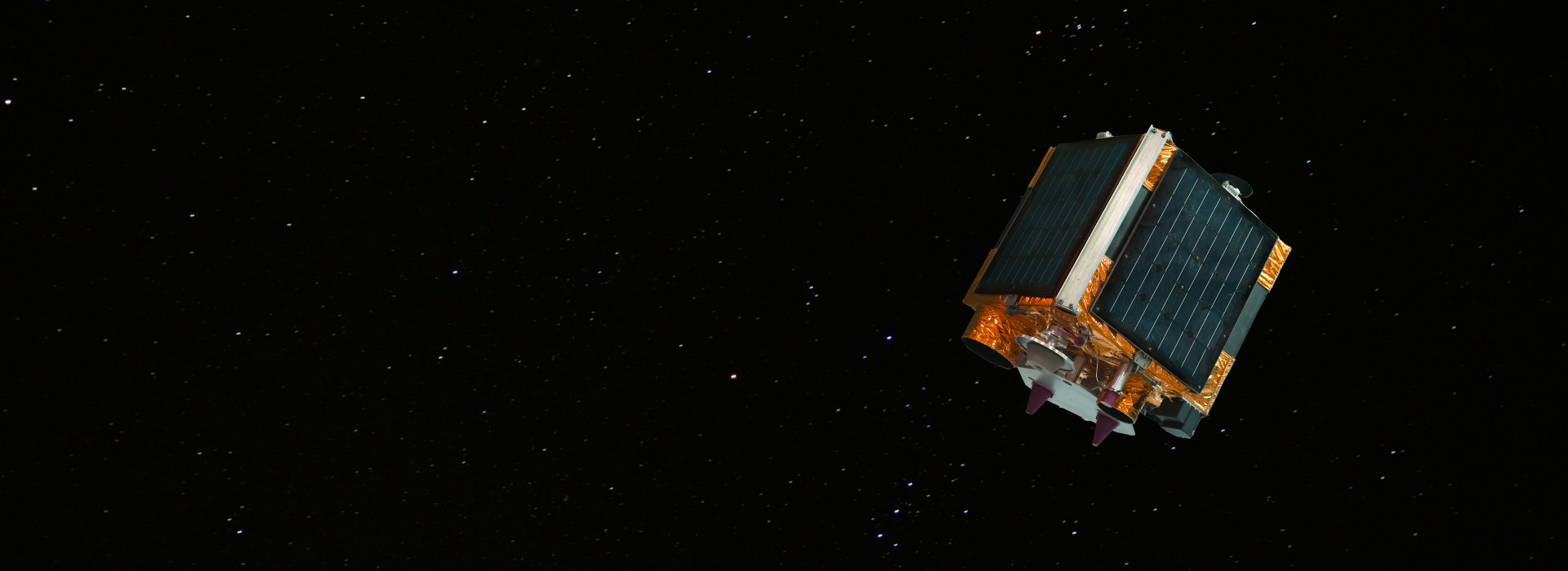
Read MoreOur commitment to excellence is unwavering, and it's reflected in every product we engineer and manufacture for space applications.
Read More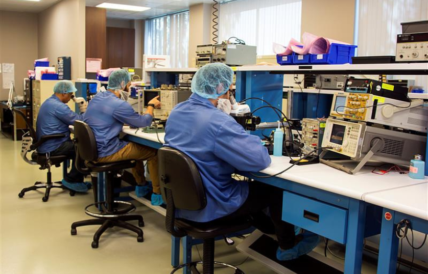
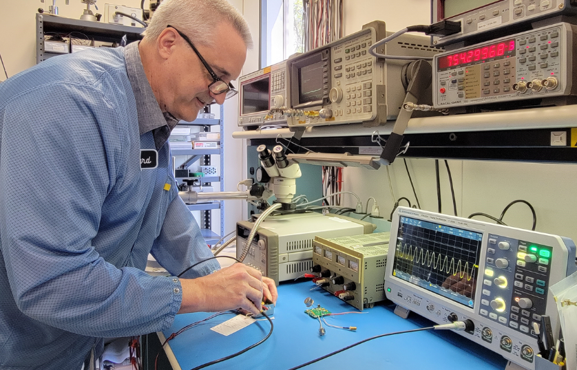
Founded in 1993, Quantic MWD (Microwave Dynamics) designs and manufactures free running and phase-locked oscillators, amplifiers, frequency converters, and frequency multipliers with a focus on the singular characteristic that matters most: performance. Quantic MWD offers a portfolio of best-in-class solutions that maximize stability and minimize noise under extreme environmental conditions, ensuring optimal precision and reliability for mission-critical and industrial defense applications.
And as a Quantic company, we’re part of an extended engineering ecosystem and powerful supply chain, defining a competitive advantage that extends to every Quantic MWD customer.
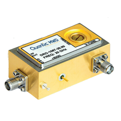
We have broadened our range of oscillators by introducing the DRO-1080 series with hermetically sealed Kovar packages. The new series complies with the MIL-PRF-38534, ASA, ESA, JAXA, ISRO, CNSA, and RFSA military and aerospace agencies standards. Available from 1 to 36 GHz.
Quantic Electronics brings together the industry’s most distinguished electronics experts, in an elite portfolio of complementary design, engineering and manufacturing businesses. Within our RF & Microwave group, our vertically integrated frequency control and timing companies collaborate closely with customers, consulting engineer-to-engineer, on the most mission-critical applications.

Since 1978, our partners at Quantic Wenzel have set the standard for ultra-low phase noise crystal oscillators, a portfolio complemented by a range of advanced frequency sources and integrated microwave assemblies to 30 GHz and beyond. Both Quantic MWD and Quantic Wenzel’s frequency control and timing products are designed into mission-critical military, space and commercial applications, and perform in the most extreme environments.
© Microwave Dynamics. dba QUANTIC MWD – ALL RIGHTS RESERVED